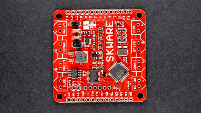
I've been taking pictures of circuits as part of the (now defunct) Omzlo One Kickstarter and Melodrama Archivesthe new follow-up "Skware" CAN-bus IoT project we are building. I've started to develop a strange pleasure for taking pictures of PCBs and I thought I'd share my experience. Sure, you can take pictures of PCBs with your smartphone and get nice results. However, if you want repeatable quality and acceptable color, you don't need to break the bank but you will need a bit more gear.
Editor's Note:
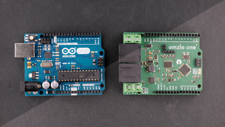
Guest author Alain Pannetrat is a self-described digital electronic fanatic who is currently working on an open-source/open-hardware Arduino-compatible IoT platform based on CAN-bus. You can follow Alain at his website Omzlo.com as well as Twitter and Github.
My recommended setup has only 3 elements:
In fact, you don't even need a DSLR. Any advanced point-and-shoot camera that has a zoom should work just as well. Warning:If you're an advanced photographer with professional lighting, macro lens and a studio, this article might hurt your eyes.
Now we can walk through taking pictures of PCBs in 7 steps:
All those steps may sound like a lot of work, but once you establish your routine, it just takes a few seconds to make a shot and a few more minutes with GIMP before you can upload your new project picture to your favorite website.
To take pictures of PCBs or products in general, it's good to have a diffused soft light source that comes from all directions uniformly. You want to reduce shadows as much as possible. A strong directional light will often create shadows, hiding details of your PCB, such as pins or components.
The solution is to use a light box, which is typically a box made of a white translucent material which is illuminated from the outside in order to give objects inside the box uniform lighting (see here for an example). There are plenty of tutorials on the net for building a light box. Just Google "diy light box".
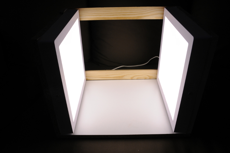
I built mine with 2 cheap outdoor square led panels and some scrap wood. The led panels produce diffused light and are placed on each side of a square box. The picture below shows the assembly almost finalized.
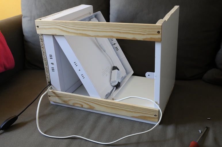
The led panels are directly plugged into the wall and can be switched on or off like a desk light. This setup is simple, solid, self-contained and easy to move around, which perfect in our small garage lab.
When taking pictures of PCBs, you typically have two options for a background: blackor white. This is a matter of personal taste and style, but I found that there are minor pros and cons for each.
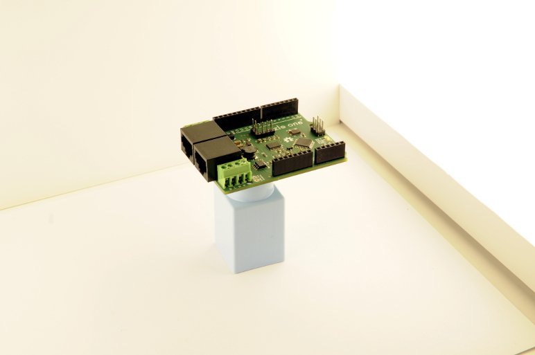
White backgrounds are ubiquitous in electronics: see SparkFun for example. The advantage of a white backgroundis that it's easy to remove later in GIMP to create a transparent background. You can then create a transparent PNG/GIF image of you PCB and merge it with an existing background on a web page. On the downside, a white background will be very sensitive to any projected shadow from your PCB. To avoid projected shadows, it's best to avoid resting the PCB directly on the background: raise it on a small object, to create a distance with the background, as shown in the picture below.
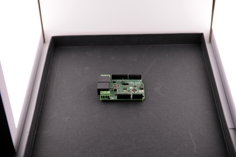
Black or dark gray backgrounds give your picture a more specific style, check out Adafruit for example. They are less flexible in terms of integration in web pages. On the other hand, they are also more forgiving of shadows: you can directly rest your PCB on the background without much worry as shown on the picture below.
Most cameras today are quite smart and they will automatically calculate the correct exposure for your shot. Beware that in some cases, the use of a black or white background can confuse your camera. A white background can cause your PCB to look too dark, while a black background may cause your PCB to look too bright. If this is the case, you can typically set your camera to underexpose or overexpose the shot a little to correct the problem.
When taking a portrait of somebody with a camera, rather than getting close to the subject, it's best to zoom as much as possible and step away as much as needed to frame the person's face in the camera. This gives much more flattering results by reducing distortions. The same applies to taking pictures of PCBs.
The actual zoom focal length range of a camera is influenced by several factors including the sensor size and the optics of the zoom. A detailed discussion of focal length is beyond the scope of this blog entry: just zoom as much as possible! My DSLR has a zoom with a focal length that goes from 17mm to 50mm, on an APS-C sensor (equivalent to 26 to 75mm on a 35mm film frame). I always zoom all the way to 50mm to take a picture of a PCB.
The picture below shows roughly the same picture taken with two different focal lengths. On the right, the picture is taken with a 12mm focal length, using a wide angle lens. On the left, the picture is taken with a 50mm focal length, using my zoom at maximum focal length. As you can see, the picture on the right has much more distortions: pin headers seem to be bending outwards.
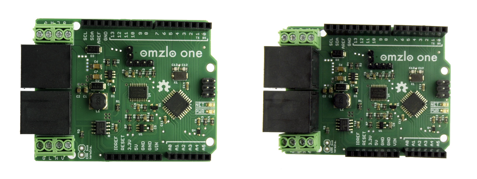
You could argue that the picture on the left has still a bit of distortion, but I think it's good enough for showcasing a PCB.
You want all of your PCB to appear in focus. The depth of field – the depth of what appears in focus on the picture – is controlled by the aperture on your camera. You want to reduce the aperture while maintaining a reasonable shutter speed. If it sounds gibberish to you, just look at your camera settings display:
You want the aperture number to be as high as possible: higher means a smaller aperture. But there is a link between speed and aperture: the smaller the apertures, the lower the speed. And when the speed gets too low, the camera will record the involuntary movement of the photographer, resulting in a blurry picture. As a rule of thumb, you don't want to go much below a speed of 1/50th of a second.
The picture below shows the same picture with 2 different apertures:
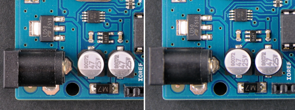
While both pictures show the circuit board in good detail, the picture on the right has less depth of field. Some components such as the DC barrel jack or the bottom female headers are a bit blurry.
On DSLRs and advanced point and shoot, you can set the camera in a mode where you can control the aperture: it's typically called mode "A". I usually pick an aperture between f/8 and f/11, which results in a speed between 1/50th and 1/100th of a second with my light box. Stronger lights will give you more flexibility.
Now you put you PCB in the light box, take a picture and view the corresponding JPEG file on your computer. In some cases, you might be surprised that the image has a strong color cast: it might look more yellowish or blueish than what you "saw" when you took the picture...
There are several reasons for this difference. The light you use in your light box is not perfect, it is a far cry from real natural light, especially if you use cheap led panels like I do. The camera may have made a wrong "guess" about the light source. Your brain will also fool you. Your computer screen might also be off a bit as well...
You can correct this color cast in GIMP to a certain degree, but it's better to minimize it from the start. To do that, you will need to set the White Balanceof your camera (often abbreviated as "WB"). I've found that trying out the predefined settings of the camera until one works reasonably well is enough (Auto, Tungsten, Fluorescent, ...).
Now it's time to take the picture. Switch on the light box and eliminate all other sources of light. Close windows and doors. Switch off the room ceiling light. This will eliminate parasite light sources that may confuse your camera. This is very important.
Center the PCB in the frame, stay steady and press the shutter!
GIMP is a free and open source image editor that works on Windows, macOS or Linux. There are plenty of online resources available on how to install and use this tool. If you are a photographer, there are much better proprietary alternatives out there, but it's hard to beat the price of GIMP and it has all the basics you need.
So you took your picture, you can now upload the resulting JPEG file in GIMP to make some final corrections, namely:
The only tool I use for color correction is the levelstool in GIMP, which you can find in the "colors" menu, as shown below.
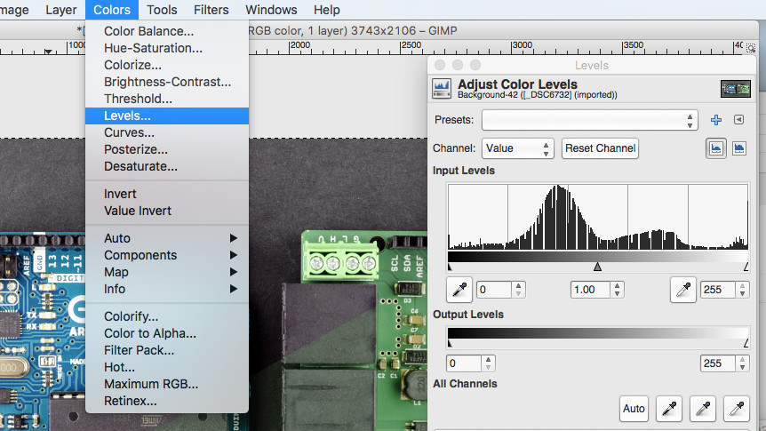
In many cases, it's enough to click on "Auto" to adjust the color and contrast of the picture: you're basically done. For other cases, I use the white point and black point "pipette" icons that are sitting next to the "Auto" button in the levels dialog box shown above:
The picture below shows an example of a correction applied. The lower right part of the picture is unprocessed while the upper left area is corrected.
Once color correction is applied, it's time to crop the picture if necessary to let the PCB fill the frame well enough.
By following the simple steps above, I've developed a pretty satisfactory approach to taking pictures in our projects. Of course, it's not perfect but it's simple enough.
There are some easy improvements to this process:
And you, what are your tips and tricks for taking pictures of your electronic projects?
Previous:The Best Gaming Concept Art of 2016
Next:Gods of War
 Virtual Reality: The True Cost of Admission (and Why It Doesn't Matter)
 Google Maps will be the built
 13 striking photos that capture India's 68th Republic Day preparations
 China's latest beauty app takes Snapchat
It's Time to Reinvent the Digital Pen
China's latest beauty app takes Snapchat
It's Time to Reinvent the Digital Pen
 Trump's voter fraud investigation may want to start with his own daughter
 Lightning struck Washington 2,200 times on Saturday night
 Watch hurricane hunters fly through Dorian’s stadium
10 Free Steam Games Worth Playing
Watch hurricane hunters fly through Dorian’s stadium
10 Free Steam Games Worth Playing
 Wikipedia knocked offline in Europe after 'malicious attack'
 NYT Connections Sports Edition hints and answers for March 4: Tips to solve Connections #162
 Wunderlist founder wants to buy his app back from Microsoft
Google Maps will be the built
Wunderlist founder wants to buy his app back from Microsoft
Google Maps will be the built
 Older people way more OK with police using facial recognition, Pew poll finds
 NYT Strands hints, answers for April 23
 CNN trolls Trump
China's latest beauty app takes Snapchat
CNN trolls Trump
China's latest beauty app takes Snapchat
 Motorola One Zoom is the most beautiful phone I've seen in years
 Google Pixel Buds Pro 2: $40 off at Amazon
 GPS trackers for kids exposed real
6 meaningful ways you can support all mamas on Mother's DayRed Sox pitcher developed carpal tunnel, may need to quit 'Fortnite'A chance alignment at a soccer match gave us the hero we deserveFacebook reportedly working on its own BitcoinA man spilled a soda in a public toilet and his shame went viralThe Boring Company completes Elon Musk's tunnel beneath L.A.Boston Dynamics says its stairGoogle's new tool lets anyone turn Street View images into VR 'tours'Google's new tool lets anyone turn Street View images into VR 'tours'Facebook bans all foreign ads related to Ireland's abortion referendumGoogle makes its privacy policy clearer so we can actually understand itLeak hints at iPhone SE 2 with notch just like iPhone XZTE ceases major operations as it tries to lift U.S. banJuul vapes will contribute to a dangerous eJust a bunch of people being big jerks on Google Street ViewReview: Xiaomi Mi Electric Scooter is all over the roads for a reasonGoogle tries to burst filter bubbles with redesigned 'News' app30 things Netflix would have to do to make me cancel my account'Disobedience' has one of the most realistic lesbian sex scenes everDisney CEO Bob Iger says there will be more Avengers movies Aziz Ansari, Guillermo del Toro stop by In Dylan Farrow slams stars for supporting both Time's Up and Woody Allen An ode to Will Smith's perfect Instagram account With Full Self The original songs in 'Schmigadoon!' perfectly capture the joy of musicals Facebook Messenger makes it easier to find perfect emoji reaction Everyone's an MVP in heartwarming 'Ted Lasso' Season 2 BBC journalist quits after discovering she earns 50% less than male counterparts Woman gets entire airplane to herself after getting booked onto flight meant for staff Who is Racy Taylor? A documentary highlights woman Oprah shouted out Luke Prokop becomes first openly gay player on NHL contract Clever artist turns Michael Wolff's 'Fire and Fury' into a hilarious pop Trump won an award from the Committee to Protect Journalists Snapchat profiles will feature 3D full How to use an Xbox controller on your iPhone The weirdly dystopian photo from the White House press briefing 2018 is already off the rails thanks to Donald Trump Now Google will display why it's showing you its search results Donald Trump just confused the word 'consensual' on Twitter NASA's Perseverance Mars rover to collect samples meant for Earth
1.0738s , 10206.1953125 kb
Copyright © 2025 Powered by 【Melodrama Archives】,Creation Information Network